PRIMARY ENGINEERING SYSTEMS
Construction Means / Methods:
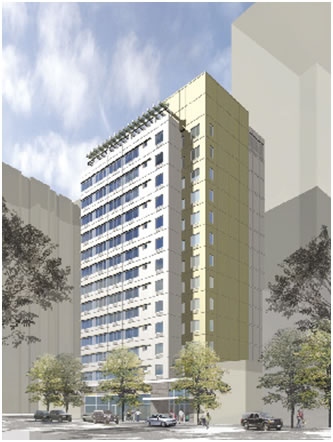
The construction process of 40 Gold Street involved overcoming several major challenges that are not regularly present in construction projects. The construction process first began back during groundbreaking in May of 2009 and is nearing the scheduled completion date in February of 2010.
As mentioned in Building Statistics I (make a link), the 40 Gold building is located on a small site in which special restrictions pose constructability and design issues. More importantly, the site is surrounded by two existing structures and two adjacent streets.
Originally 40 Gold Street was going to be designed as a concrete structure; however, after site reconnaissance data and geotechnical tests revealed poor site conditions, it was determined that steel would be the optimal material for the primary structural system. Due to nearby existing foundations, the construction process had to be conducted with great awareness so as not to disturb the existing foundations. During excavation, existing foundation elements, walls, and even streets required extra support and shoring for both temporary and long term structural support. Due to cost and constructability, the foundation was designed so as to avoid the necessity for underpinning of nearby structures. As a consequence, moment frames and column lines are net positioned in the ideal linear fashion.
The foundation system was originally going to be comprised of driven piles; however, the construction of this type of foundation posed the threat of vibration and settlement damage to adjacent structures. Therefore, micro piles are used for the foundation system.
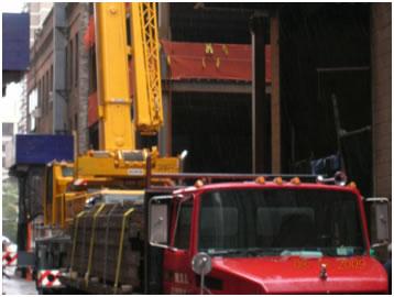
Another major issue during construction was the timetable. A crane was required for construction; however, due to space limitations the crane had to be positioned on 40 Gold Street. Unfortunately, this required the street to be closed, and the city of New York issued a deadline by which the crane must be removed from the street. As a result, the construction scheduling and planning became extra critical when introducing into the equation the limited time for crane use.
Structural System:
Gravity loads are transferred from a typical 2”-18 gage metal deck with 2-1/2” light weight concrete topping to the building steel skeleton. Primarily composed of W10 and W12 shapes, the steel framing is laid out in a very uniform and efficient manner. The framing layout features primarily rectangular bays of minimal size, and few irregularities are present throughout the framing design. Gravity loads are distributed in a symmetrical manner down through the structure. Ultimately, building loads are transferred to large 36” deep pile caps and then a system of micro plies transfers loads to the soil.
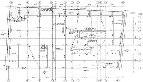
The Lateral system employed in 40 Gold Street includes 4 moment frames spanning East/West across the building and 5 braced frames which utilize HSS shapes as diagonal cross braces. The moment frames are skewed due to the non linear column lines which are a direct consequence of footings being moved to avoid disturbing nearby foundations. The lateral elements are laid out symmetrically. From first look, it appears the Center of Rigidity is at or near the Building Center of Mass, and so torsion effects should not be of major concern.
Mechanical System:
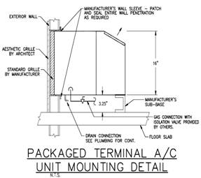
40 Gold Street is equipped with packaged thru the wall AC units (see figure below) which are traditionally found in similar residential buildings. Each apartment has the ability to regulate its own space using its own gas heated / electric Air Conditioning system. Tenants may regulate conditions using a two-speed room air motor (hi and low A/C and hi and low Heating). In addition, tenants may use the fan cycle switch to permit continuous indoor fan operation. These units operate with a total cooling capacity of either 9,800, 11,700, or 16,000 BTU (depending on model and apartment size) and a heating rated input of 12,000 BTUH – 20,000 BTUH (depending on model and apartment size). Each apartment is also equipped with operable windows to enhance cross / natural ventilation.
The rooftop houses the boiler room and several major mechanical items. A REZNOR rooftop packaged air-conditioning unit operates at 3600 CFM supply and gas heating functions based on an entering temperature of 10 degrees Fahrenheit and a leaving temperature of 85 degrees.
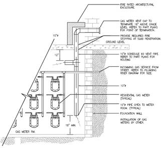
The cellar and first floor spaces are accommodated with Air cooled Air handler units all of which have 11,300 BTUH total capacities. In the cellar, the gas meter room is located, and has its own separate venting mechanism as required by code (shown above).
As one can see below in the boiler room schematic, (3) 300 MBH input capacity, natural gas fired boilers are located on the roof and operate at 18 GPM. The boilers function in conjunction with the 3 separate pairs of supply and return Hot Water Pumps that can handle a maximum temperature of 210 degree Fahrenheit. The boilers and pumps service all residential and retail spaces.
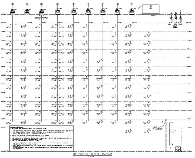
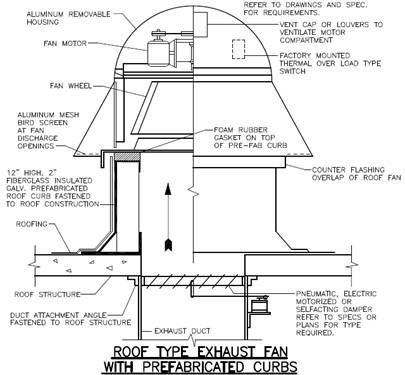
As illustrated by the figure below, sheet metal ductwork risers connect toilet rooms, kitchenettes, and elevator rooms with rooftop exhaust fans which are also detailed below.
Lighting/Electrical:
An assortment of lights is used throughout 40 Gold Street. The retail façade facing the sidewalk is equipped with exterior lighting to both draw attention and for safety purposes. For the interior spaces, 24”x48” and 24”x24” fluorescent light fixtures are common. Down lights, wall mounted sconces (5’ 6” AFF), wall washers, and pendant light fixtures are also found in the building. Hallways, elevators, and lobbies are properly lit and equipped with lighted exit signs.
Critical locations such as the elevator control room are carefully lit. The control room meets the required illumination value of 200 lx (19 foot candles) measured at floor level. Emergency power is provided by a 120 v power circuit for lighting of elevators.
Limited information is available regarding electrical and telecommunication systems. It is known that each elevator is provided with one dedicated outside telephone line.
ADDITIONAL ENGINEERING SUPPORT SYSTEMS
Transportation:
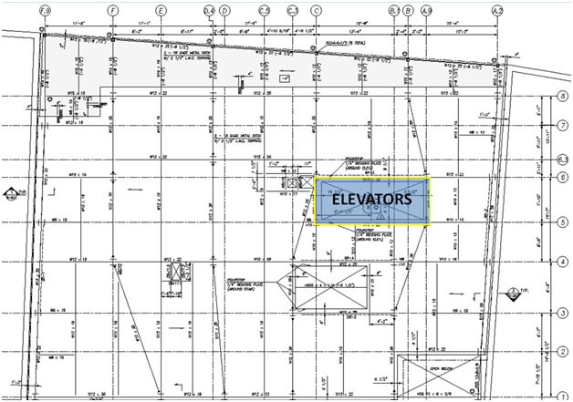
The residential areas are serviced by two OTIS Elevators. The elevators are finished with a fine terrazzo flooring material and an impressive brass paneling adorns the doors and interior walls. Both passenger elevators have a 2000 lb capacity and operate a 300 FPM speed. One elevator rises 161’2” with 15 landings and the other elevator rises 150’8” with 14 landings. The two elevators are located adjacent to eachother and are accessible to residents at the ground floor lobby. The elevator core is located near the core of the building as shown in the figure below.
The total car weight for each elevator is 4,730 lbs and each elevator is supported with five 5/8” 8x19 steel hoist cables that have 23,000 lb breaking strength. Machine beams are designed as W10x39s. NO counterweight system is used. The cab height is 9’-7” and each elevator has a properly designed DTFS. The Distance from car rail to front load point is designed between the required minimum of 2’ 11-1/16” and maximum of 4’ 9-3/4” length. The elevator power supply is documented as 208V – 3PH – 60 HZ.
Fire Protection:
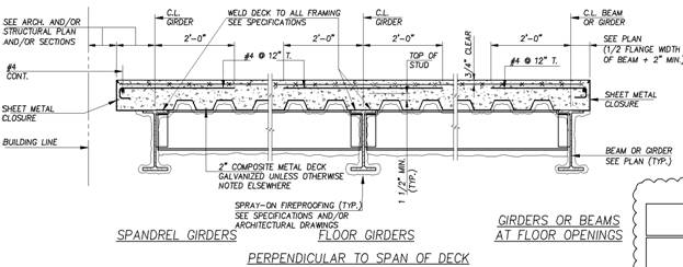
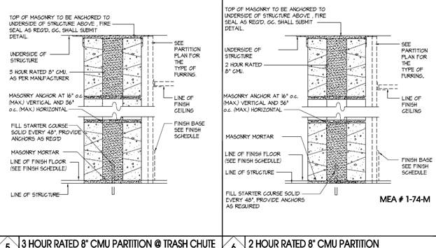
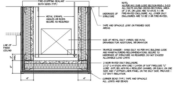
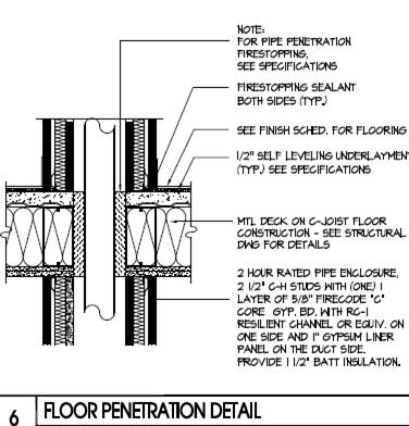
The structural steel is protected with spray on fireproofing as indicated in the figure below. Wall partitions and floor penetrations are also all treated according to code. Two and Three hour fire ratings are achieved as shown below. Duct work is almost all protected with a two hour fire rated assembly which includes 2-1/2” C-H studs with 1 layer of 5/8” fire code “C” core gypsum board with RC-1 Resilient Channel and 1” gypsum liner panel. On the duct side 1 1/2” batt insulation is provided. Party walls and corridor walls are comprised of a CMU assembly that provides a 2 hour fire rating. Floor penetrations utilize fire dampers.
Each apartment is separated from the corridor and other apartments by 2 hour fire rated walls. Ductwork and mechanical areas are also isolated with 2 hour ratings. Walls between 40 Gold Street and the adjacent structures are 3 hour rated.